ONE OF THE UK'S LARGEST SUPPLIER OF REPLACEMENT KUBOTA & BETA MARINE PARTS

CUSTOMER SERVICE TEL : +44 1324 633266 EMAIL : INFO@JEMENGINES.CO.UK
FUEL INJECTION PUMP - SPILL TIMING
Spill timing is measuring the moment at which injection commences. There are a few variation of how to check the spill timing - these are explained below !


SPILL TIMING - WITH TIMING MARKS
Connect a gravity fuel supply to the fuel inlet connection. It is best to use a metal 5 litre can and solder a hose connection into the base of the can. Connect a short piece of fuel hose to the can nipple and to the fuel pump. Partially fill the can with fuel oil and secure the can above the engine (approx 50cm). Remove number one injection pipe completely. Slacken number one delivery valve holder and continue to slacken until fuel starts to bleed out. At this point lower the temporary fuel supply to below the fuel pump level until the fuel stops bleeding from the slackened delivery valve. Remove the delivery valve holder completely then with small pointed pliers remove the delivery valve spring and then lift out the actual delivery valve core. It is good practice to place the valve and spring in a small container with fuel in it a small lid off an aerosol is good. Refit the hex delivery valve holder and tighten. Fit a swan neck spill pipe for testing purposes.
It is best to clean the degree calibration marks on the flywheel to make them more visible, also a torch or hand lamp will be helpful. If a stop solenoid is fitted and is the de-energize to stop type this must be removed, also set the throttle to full. Rotate the crankshaft in the correct direction of rotation until top dead centre, compression stroke number one cylinder. Lift the fuel can above the engine and at this point no fuel should be running from the swan neck spill pipe.
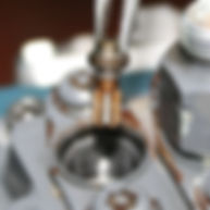
Turn the crankshaft back approx a quarter turn, fuel should now be running from the spill pipe. Now turn the crankshaft in the correct direction of rotation. At thesame time of turning the crankshaft a close eye should be kept on the flow of fuel from the swan neck spill pipe. When the fuel slow start to slow down during turning the crankshaft the crankshaft turning effort should be slowed down to a careful creep. A long bar should be used in order to achieve controlled accurate turning. Continue to slowly turn the crankshaft until the fuel flow becomes dripping and continue turning the crankshaft more slowly until the drips stop. This is the point at which injection commences. Once the point of injection starts has been determined, the degree markings on the flywheel can now be read against the index pointer or mark.


FUEL RUNNING

FAST DRIPS

STOPPED DRIPPING
SPILL TIMING - WITHOUT TIMING MARKS
In some cases the timing marks are inaccessible or not available. It is possible to create temporary timing marks on the front pulley.
It is necessary to remove the rocker cover and injectors, also remove No 1 injector pipe, also make sure the fan belt is tight as the engine will be turned by the fan blades.
First find tdc. This can be done by using a large screwdriver. Lever down slightly (3-6mm) one of the valves on No 1 cylinder, now with the valve held slightly open rotate the crankshaft by turning the fan. When No 1 piston is at or approaching tdc this can be felt at the screwdriver. Once the piston has contacted the valve rotate the crankshaft back and forward until tdc has been determined. Now make a fine index mark on the front crankshaft pulley and timing cover with a good line of sight and not obscured.
Measure the diameter of the pulley as accurate as possible (best in mm) an example of how to calculate the temporary timing marks, if say the pulley diameter is 150mm, and the required timing mark is 21 degrees btdc.
Diameter x 3.142 = circumference divided by 360 = distance on the circumference of the pulley per one degree, then multiply this figure by 21 to find out the circumference distance for 21 degrees btdc. 150 x 3.142 = 471.3mm divided by 360 = 1.30mm per one degree x 21 27.3mm.
Measure a distance of 27.3mm in front of the tdc mark (this is on the clockwise side of the tdc mark). This is now the 21 degrees btdc spill mark. This mark can now be used to time the injection pump as mentioned in the previous
How to find tdc top dead centre, compression stroke number one cylinder.
Remove the rocker cover, turn the crankshaft in the correct direction of rotation until therockers for No 1 cylinder are rocking. This is the point where the exhaust valve is closed and the inlet valve is starting to open. At this point tdc should be visible on the flywheel. At this point turn the engine back against rotation approx ¼ turn, now turn forward with rotation until spill cut off occurs as mentioned in previous description.
Fit the swan-neck spill pipe. You are now ready to follow our "Spill Timing" instructions
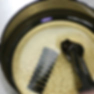
How to make Spill Pipe - using old Injector Pipe ........


A. Fast fuel flow
Cut off excess pipe as shown
Dress end of pipe at taper
and blow through to remove
swarf.
Your finished spill pipe should look like this.
B. Restricted fuel flow, slowing down to 'fast'
dripping
If you don't want to make one yourself, we have a few in stock.....click here......
C. Last drip - this is spill cut off point.